RL Blogs
By Mahans Thermal Products
Jun 05, 2019Choosing the right design for heat exchanger applications. |
| One of the most important design considerations one must make when designing a shell and tube heat exchanger is fluid selection. Choosing the right fluids and selecting which fluid will be used in the shell side and which will be used on the tube side, often affects other design considerations like zone definition, area of the exchanger, flow rates, and the materials that may be best suited to the purpose of your exchanger design.
Although fluid selection often includes intricate decisions based on factors like thermal stability, pressure considerations, economy, and pumpability, there are some basic categories of fluids that can help to narrow down your selection based on the general properties of the fluids.
BASIC FLUID CATEGORIES INCLUDE:
Based on your temperature requirements for your heat exchanger, make a selection between the above categories of fluid. If your temperature requirements exceed 175 ̊C or 350 ̊F, then you should probably consider the synthetic organic or the silicone based fluids. If your requirements are for temperatures that are lower than 350 ̊F, then inhibited glycol-based fluids are most likely best suited for the heat exchanger.
Once you have chosen your fluids, it is time to decide which fluid is best for the shell side and which is best for use on the tube side. Although there are numerous factors to consider, there are some basic rules that can help you to determine which fluid is best suited to the tube and which is best for the shell side.
FACTORS TO DETERMINE THE BEST FLUIDS:
PRESSURE
If you are designing a heat exchanger for high pressure applications, then you need to make a decision about where to place the high-pressure fluids. Choosing to place the high pressure fluid on the tube side allows you to reduce or minimize the exchanger manufacture cost.
Since the diameter of the tubing is smaller on the tube side, you will most likely require less material with high-pressure ratings on the tube side than on the larger shell side. Metal thickness on the tube side will carry a higher pressure rating than the same metal thickness on the larger shell side that may have cost implications for your design.
FOULING
Another consideration to take into account when selecting the fluids for the shell and tube sides is the potential of the liquids you have chosen to foul. Essentially, this consideration is based on how easy it will be to clean the heat exchanger and the implications of fouling for the overall function of the heat exchanger.
To make the right choice, you need to consider the heat exchanger configuration you have chosen to work with. Straight tubes, for example, are far easier to clean than U-tubes. A fixed tubesheet may make the shell side of your heat exchanger impossible to clean, in which case a fouling liquid would be an extremely bad idea. A square tube pattern can make the shell side of your shell and tube heat exchanger easier to clean, allowing you to place your fouling liquid in this area.
Essentially, the prime considerations, in terms of fouling, are how easy it will to clean the exchanger and the potential of fouling to ruin the system. If the liquid is prone to fouling and the shell side is going to be almost impossible to clean, you should rather place the liquid on the tube side.
If the shell side is the better option for the fouling liquid, then fouling reduction steps like the addition of helical baffles may be the best solution, assuming that your fouling liquid has to be placed on the shell side.
The type of fouling involved may also help you to make the best decision about liquid and materials, and on which side to place the fouling liquid.
There are various different types of fouling, depending on the conditions of the heat exchanger and the fluid selection. Common types of fouling include crystallization, organic growth, sedimentation, fouling due to chemical reaction coking, and fouling due to chemical corrosion.
CRYSTALLIZATION
Fouling due to crystallization occurs when the solubility of salts naturally present in certain types of fluids are sensitive to temperature. If the fluid is heated during the cooling process, salts may dissolve and then crystalize when the liquid cools. This heating, then cooling often results in the crystals forming as scale on the surface. Selecting another liquid or adjusting the temperatures of the heat transfer may offer solutions in this type of case.
SEDIMENTATION
Fresh water as a fluid choice can result in the deposition of sand, rust, or other compounds, and this must be taken into account when choosing the right side for these types of liquids. Adjusting the velocity of the heat exchanger may also offer a solution where these types of liquids are chosen.
BIOLOGICAL ORGANIC GROWTH
The exchanger materials and fluids must be carefully considered in terms of their chemical composition. Where the materials used and the fluids chosen can react with one another, these chemical reactions must be taken into account, and potential resultant fouling must be considered. Where there is a high chance of this type of fouling, changes in either material or liquid should be seriously considered.
FOULING DUE TO CORROSION
Biological growth is not the only reaction that can occur where materials chosen are less than ideal. Where fluids and materials react in the form of corrosion, the fluid can destroy the surfaces of the heat exchanger, and this can result in expensive repairs. Corrosion can affect the heat transfer capabilities of the equipment, and it is therefore vital to consider the properties of both the materials and fluids to avoid corrosion where possible.
FOULING DUE TO CHEMICAL REACTION COKING
Chemical reaction coking occurs where the liquid chosen deposits hydrocarbons in high temperature applications. In this case, adjusting the temperature between the heat transfer surface and the fluid may offer a solution.
MATERIAL INVOLVED
Another consideration, when choosing your liquids and deciding which is the right side to place them, is about the materials used to construct the heat exchanger itself and the nature of the fluids you have chosen to include in your design.
Corrosive fluids will cause a certain amount of damage to the system. To offset the potential corrosive damage, you will need to select corrosion resistant alloys and materials, and these will drive up the costs of your heat exchanger design.
Choosing to place the corrosive liquid on the tube side rather than the shell side can help to limit the damage caused and the costs involved in replacing these components. Since only the tube side will require the more expensive materials rather than the entire exchanger, choosing the tube side may make more sense financially and in terms of replacement costs.
POTENTIAL PRESSURE DROPS
Where the fluid chosen has the potential for pressure drops or a low pressuredrop, you should place this fluid on the shell side of the exchanger. If the shell side pressure drops need to be reduced further, then the following strategies can be considered:
VAPOR
If you are working with vapors, or require vapor in the heat exchanger, then it is best to use the vapor on the shell side rather than on the tube. Vapors normally require higher volumes, and they offer a lower heat-transfer coefficient. Placing vapors on the shell side can help to reduce pressure drops for a particular volume. It will also generally offer higher heat transfer coefficients.
CONDENSING SERVICES
If condensing services are required, you should try to place the condensing fluid on the shell side, rather than the tube side, although there are also other considerations that need to be taken into account for condensing services.
Where the condensing liquids are relatively pure, and where the condensing range between the liquids is relatively narrow, the configuration of the exchanger may not be that important, but where mixtures have a wide condensing range configuration, the exchanger may require more consideration. With wide condensing range mixtures, flow patterns inside the exchanger should be carefully chosen to ensure that the liquids and vapors inside the exchanger remain mixed.
Shell-side velocity must be high enough to reduce the vapor and liquids separating inside the exchanger. Liquid that drops out can make the vapor leaner, and this can affect the temperature that is required to condense from the vapor.
Wide condensing range mixtures may also require that you design an exchanger where the fluid leaves from the bottom to help force liquid into the vapor mix. You may also need to consider your choice of baffling, selecting a horizontal, rather than a vertical baffle cut.
VISCOUS SERVICES
Viscous services can require complex decision making, and you need to consider various factors and be ready to make a variety of compromises in terms of your heat exchanger design.
If you have a viscous fluid on the tube side, it may result in low heat transfer and a high pressure drop, which may mean that a shell-side application in this case may be preferable. Choosing the shell-side, however, may not be without disadvantages.
A high pressure drop on the shell side may result in vibration damage and may also require flow bypassing around the baffles. If, however, a shell-side application is necessary, then there are shell-side modifications that may be made to limit the damage and other disadvantages.
SOLIDIFYING SERVICES
Although shell and tube exchangers can be designed for services that have a high risk of freezing or solidification, wherever possible, try to avoid using these types of heat exchangers in these types of situations, since the chances of needing an entire exchanger replacement are high.
If you have to design a heat exchanger, and there is a fluid at risk of solidification, selecting the tube side for this fluid may possibly be the best choice. The tubes can be bundled and more easily replaced than the shell side. If the shell side is solid, it often results in replacing the entire exchanger.
Shell side liquids that freeze do offer the advantage of being able to use external heating to help melt the frozen matter, which may allow the exchanger to be brought back into service.
Fluids that can freeze can plug certain areas of the exchanger. This can affect the velocity within the exchanger, and affect the heat exchange and temperatures within the exchanger, which could result in the fluid setting solid. Freezing fluids, therefore, often result in large areas where the exchanger has set solid.
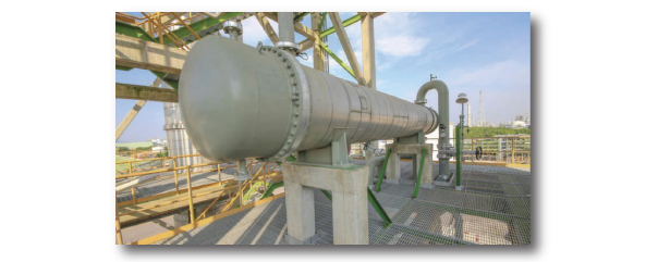
SHELL & TUBE HEAT EXCHANGER DESIGN
The above rules and suggestions are merely intended as guidelines to help simplify the process of choosing materials, liquids, and selecting the right sides for those liquids.
Shell and Tube heat exchanger design is a complex undertaking with various factors influencing choice of material and design. Approaching a professional organization for design, repair, and cleaning of your heat exchanger can help to ensure you have well-maintained equipment. |
|
|